Propuesta de montajes.
1.- Sin programación
Estos montajes nos enseñarán a interpretar los esquemas electrónicos y montarlos en una protoboard. También se trabajará con componentes básicos (resistencia, led y pulsador) y se realizá el cableado de inteconexión.
Se introducirán conceptos como:
-
Corriente, Intensidad y Resistencia. Potencia
-
Corriente alterna y corriente continua.
-
Digital y analógico.
-
Polarizado y No polarizado.
-
Serie y paralelo.
Para estos montajes no es necesario utilizar la placa Arduino. Se podría sustituir por una pilas o una fuente de alimentación de 5V como las de los móviles.
Para estos montajes necesitaremos:
-
Fuente de alimentacion o Ordenador, placa Arduino y cable USB.
-
Protoboard y cables de interconexión.
-
Leds y sus correspondientes resistencias de protección.
-
Pulsadores
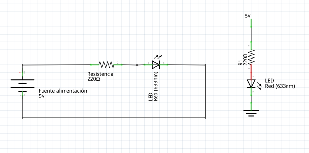
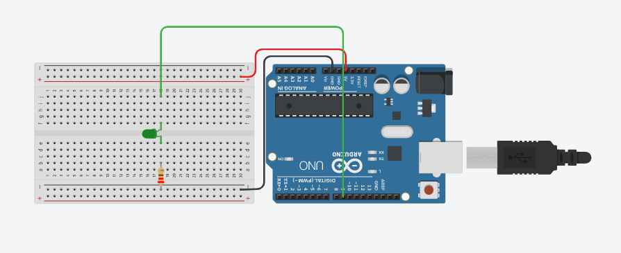
Led directo
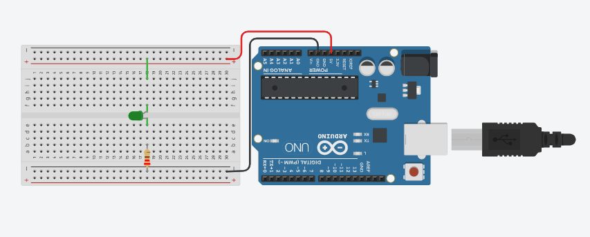
Realiza un montaje de un led que esté siempre iluminado. Recuerda que el led necesita una resistencia de protección. Utiliza Arduino como fuente de alimentación usando solamente los pines 5Vy GND.
Arduino
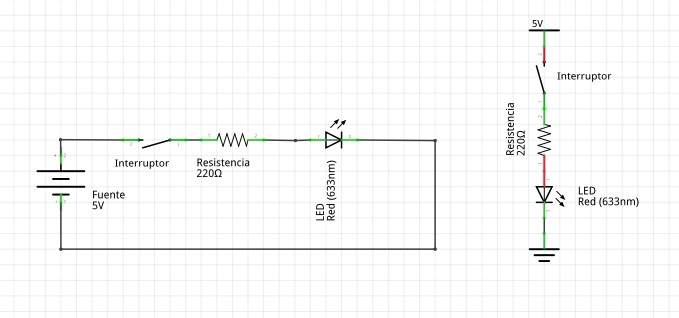
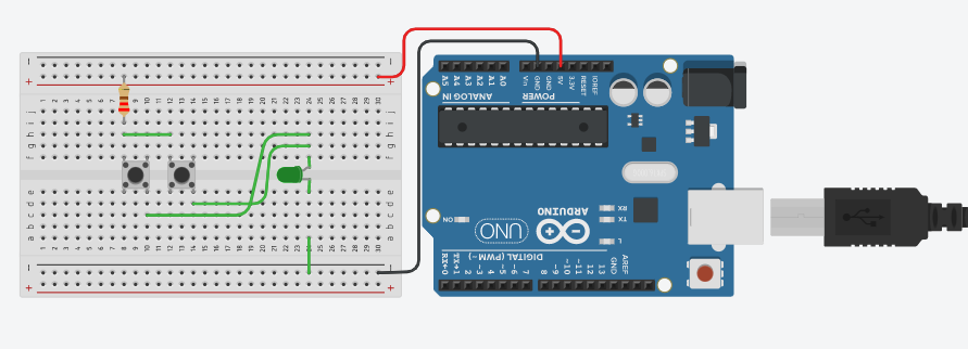
Led y pulsador en serie
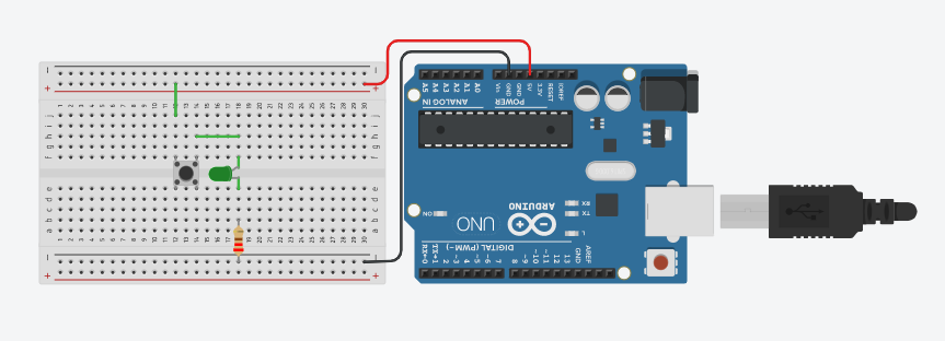
Realiza un montaje de un led con un pulsador en serie. Recuerda que el led necesita una resistencia de protección. Utiliza Arduino como fuente de alimentación usando solamente los pines 5Vy GND.
Arduino
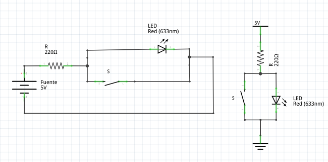
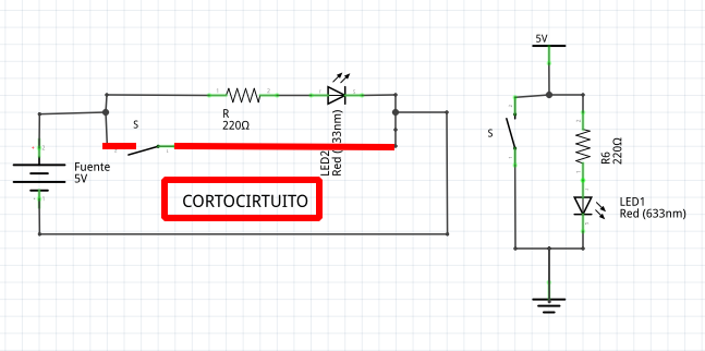
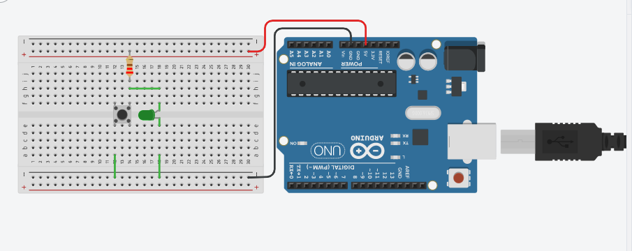
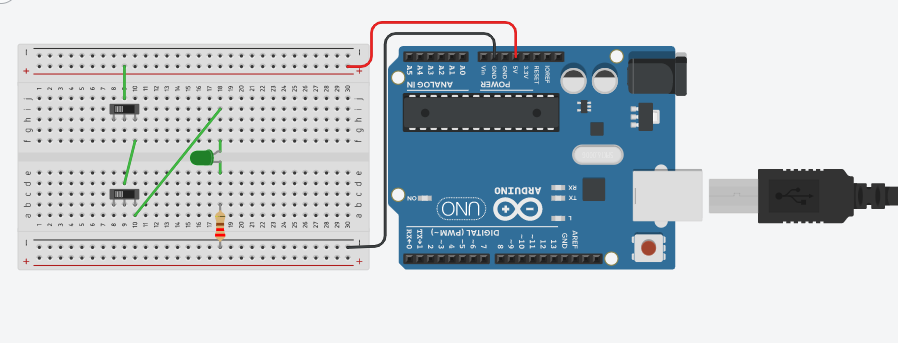
Led y pulsador en paralelo
Realiza un montaje de un led con un pulsador en paralelo. Recuerda que el led necesita una resistencia de protección. Utiliza Arduino como fuente de alimentación usando solamente los pines 5Vy GND.
Arduino
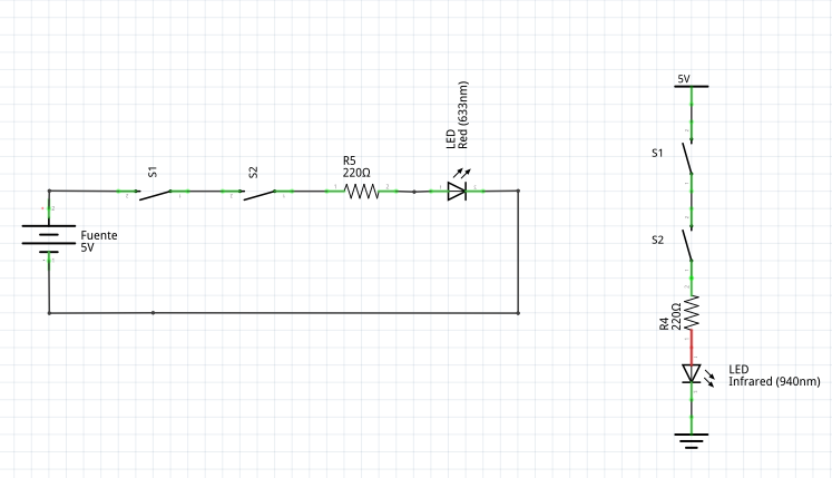
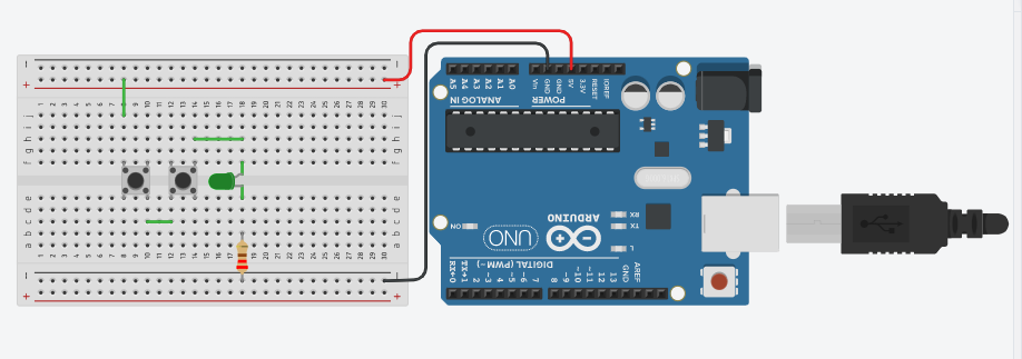
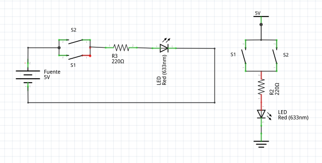
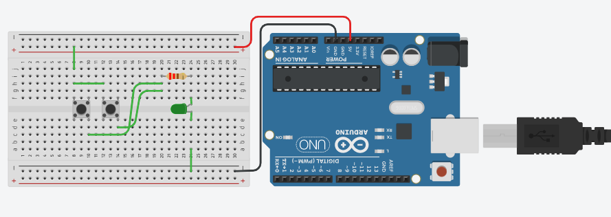
Led y dos pulsadores en serie
Realiza un montaje de un led con un pulsador en paralelo. Recuerda que el led necesita una resistencia de protección. Utiliza Arduino como fuente de alimentación usando solamente los pines 5Vy GND.
Arduino
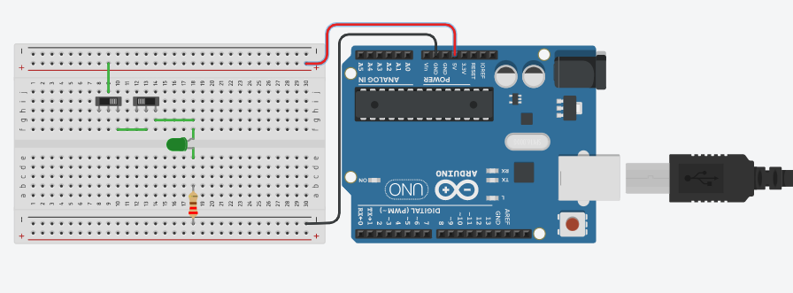
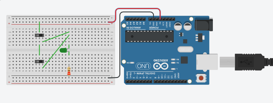
Led y dos pulsadores en paralelo
Realiza un montaje de un led con un pulsador en paralelo. Recuerda que el led necesita una resistencia de protección. Utiliza Arduino como fuente de alimentación usando solamente los pines 5Vy GND.
Arduino
2.- Con programación
Una vez tengamos cierta soltura con la electrónica necesaria para usar una protoboard vamos a introducirnos en la programación de la placa Arduino. Para ello necesitamos tener instalado el Entorno de Desarrollo Arduino (IDE Arduino). En este entorno escribiremos nuestros programas como si de un editor de texto se tratara y se los enviaremos a la placa Arduino por el cable USB. Recordad que antes de cargar el programa hay que comprobar que hemos seleccionado la placa Arduino correcto y el puerto de comunicción correcto.
Se introducirán conceptos como:
-
Entorno de programación
-
Lenguaje de programación.
-
Programación estructurada. Funciones.
-
Conexión de la placa Arduino. Puerto
2.1.- Salida digital.
Se introducirán conceptos como:
-
Funciones setup() y loop()
-
Funciones digitales: digitalWrite()
-
Función de espera: delay();
-
Variables. Constantes: LOW, HIGH
-
Comentarios
-
Función valor aleatorio: ramdon()
-
Estructuras repetitivas: for
-
Componentes básicos:
-
Diodo led
-
Resistencia
-
Para estos montajes necesitaremos:
-
Ordenador con IDE Arduino instalado.
-
Placa Arduino y cable USB.
-
Protoboard y cables de interconexión.
-
Leds y sus correspondientes resistencias de protección.
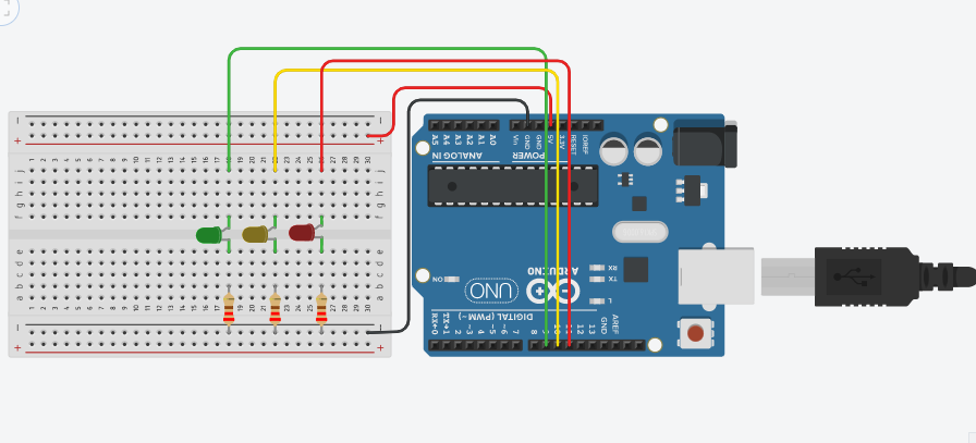
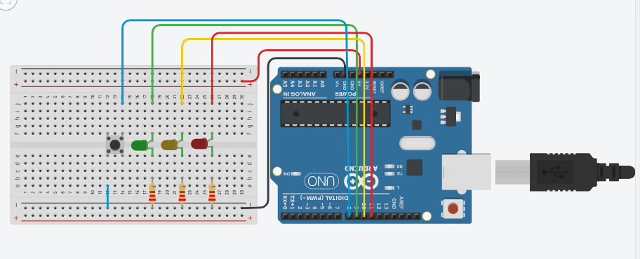
Led parpadeo constante (blink)
Realizar un montaje en el cual un led parpadee.
Nota: el cable rojo de 5V no se utiliza.
Código Arduino
const int led_rojo = 9;

void setup()
{
  pinMode(led_rojo, OUTPUT);
}

void loop()
{
  digitalWrite(led_rojo, HIGH);
  delay(200);

  digitalWrite(led_rojo, LOW);
  delay(200);
}
Ampliación con 3 leds.
Led parpadeo rítmico (200,200,500)mseg
Realizar un montaje en el cual un led parpadee de forma rítmica. Realizando pausas de 200, 200 y 500 milisegundos.
Código Arduino
int led = 9;

void setup()
{
  pinMode(led, OUTPUT);
}


void loop()
{

  digitalWrite(led, HIGH);
  delay(200);
  digitalWrite(led, LOW);
  delay(200);

  digitalWrite(led, HIGH);
  delay(200);
  digitalWrite(led, LOW);
  delay(200);

  digitalWrite(led, HIGH);
  delay(500);
  digitalWrite(led, LOW);
  delay(500);


}
Led parpadeo aleatorio (ramdon)
Realizar un montaje en el cual un led parpadee de forma aleatoria. Para ello se utilizará la función ramdon. Delimitar los valores entre 100 y 800 milisegundos.
Código Arduino
int led_rojo = 9;
int led_amarillo = 10;
int led_verde = 11;
int espera;
void setup()
{
pinMode(led_rojo, OUTPUT);
pinMode(led_amarillo, OUTPUT);
pinMode(led_verde, OUTPUT);
}
void loop()
{
espera = random(80,350);
digitalWrite(led_rojo, HIGH);
digitalWrite(led_amarillo, HIGH);
digitalWrite(led_verde, HIGH);
delay(espera);
digitalWrite(led_rojo, LOW);
digitalWrite(led_amarillo, LOW);
digitalWrite(led_verde, LOW);
delay(espera);
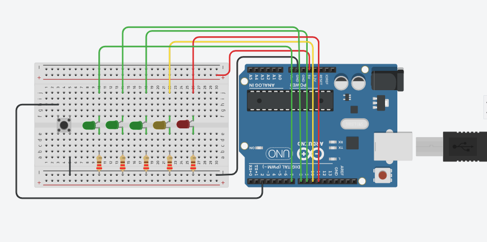
}5 Leds parpadeo sincronizado (xoxox,oxoxo)
Realizar un montaje con 5 leds. Estos leds deben parpadear según su orden par o impar. Es decir, primero los leds de las posiciones 1, 3 y 5 y después los de las posiciones 2 y 4. Se puede ampliar este montaje con esperas aleatorias.
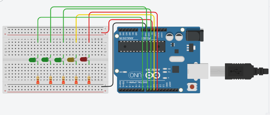
Nota: el cable rojo de 5V no se utiliza.
Código Arduino
int led_1 = 7;
int led_2 = 8;
int led_3 = 9;
int led_4 = 10;
int led_5 = 11;

void setup()
{
  pinMode(led_1, OUTPUT);
  pinMode(led_2, OUTPUT);
  pinMode(led_3, OUTPUT);
  pinMode(led_4, OUTPUT);
  pinMode(led_5, OUTPUT);
}


void loop()
{
  digitalWrite(led_1, HIGH);
  digitalWrite(led_2, LOW);
  digitalWrite(led_3, HIGH);
  digitalWrite(led_4, LOW);
  digitalWrite(led_5, HIGH);
  delay(200);

  digitalWrite(led_1, LOW);
  digitalWrite(led_2, HIGH);
  digitalWrite(led_3, LOW);
  digitalWrite(led_4, HIGH);
  digitalWrite(led_5, LOW);
  delay(200);
}
Ampliación con espera aleatoria.
5 Led parpadeo ida y vuelta
Reutilizando el montaje anterior de 5 leds hacer que se vaya iluminando un led cada vez por orden. Una vez que se llega al último leds volver en orden decreciente. Si analizas el problema, debe haber 8 pasos en los que se ilumine un led cada vez.
x0000 0x000 00x00 000x0 0000x 000x0 00x00 0x000
Código Arduino
int led_1 = 7;
int led_2 = 8;
int led_3 = 9;
int led_4 = 10;
int led_5 = 11;

void setup()
{
  pinMode(led_1, OUTPUT);
  pinMode(led_2, OUTPUT);
  pinMode(led_3, OUTPUT);
  pinMode(led_4, OUTPUT);
  pinMode(led_5, OUTPUT);
}

void loop()
{
  digitalWrite(led_1, HIGH);
  digitalWrite(led_2, LOW);
  digitalWrite(led_3, LOW);
  digitalWrite(led_4, LOW);
  digitalWrite(led_5, LOW);
  delay(200);

  digitalWrite(led_1, LOW);
  digitalWrite(led_2, HIGH);
  digitalWrite(led_3, LOW);
  digitalWrite(led_4, LOW);
  digitalWrite(led_5, LOW);
  delay(200);

  digitalWrite(led_1, LOW);
  digitalWrite(led_2, LOW);
  digitalWrite(led_3, HIGH);
  digitalWrite(led_4, LOW);
  digitalWrite(led_5, LOW);
  delay(200);

  digitalWrite(led_1, LOW);
  digitalWrite(led_2, LOW);
  digitalWrite(led_3, LOW);
  digitalWrite(led_4, HIGH);
  digitalWrite(led_5, LOW);
  delay(200);

  digitalWrite(led_1, LOW);
  digitalWrite(led_2, LOW);
  digitalWrite(led_3, LOW);
  digitalWrite(led_4, LOW);
  digitalWrite(led_5, HIGH);
  delay(200);

  digitalWrite(led_1, LOW);
  digitalWrite(led_2, LOW);
  digitalWrite(led_3, LOW);
  digitalWrite(led_4, HIGH);
  digitalWrite(led_5, LOW);
  delay(200);

  digitalWrite(led_1, LOW);
  digitalWrite(led_2, LOW);
  digitalWrite(led_3, HIGH);
  digitalWrite(led_4, LOW);
  digitalWrite(led_5, LOW);
  delay(200);

  digitalWrite(led_1, LOW);
  digitalWrite(led_2, HIGH);
  digitalWrite(led_3, LOW);
  digitalWrite(led_4, LOW);
  digitalWrite(led_5, LOW);
  delay(200);
}
Código Arduino (Versión simplificada)
int led_1 = 7;
int led_2 = 8;
int led_3 = 9;
int led_4 = 10;
int led_5 = 11;
void setup()
{
pinMode(led_1, OUTPUT);
pinMode(led_2, OUTPUT);
pinMode(led_3, OUTPUT);
pinMode(led_4, OUTPUT);
pinMode(led_5, OUTPUT);
}
void loop()
{
digitalWrite(led_1, HIGH);
digitalWrite(led_2, LOW);
digitalWrite(led_3, LOW);
digitalWrite(led_4, LOW);
digitalWrite(led_5, LOW);
delay(200);
digitalWrite(led_1, LOW);
digitalWrite(led_2, HIGH);
digitalWrite(led_3, LOW);
digitalWrite(led_4, LOW);
digitalWrite(led_5, LOW);
delay(200);
digitalWrite(led_1, LOW);
digitalWrite(led_2, LOW);
digitalWrite(led_3, HIGH);
digitalWrite(led_4, LOW);
digitalWrite(led_5, LOW);
delay(200);
digitalWrite(led_1, LOW);
digitalWrite(led_2, LOW);
digitalWrite(led_3, LOW);
digitalWrite(led_4, HIGH);
digitalWrite(led_5, LOW);
delay(200);
digitalWrite(led_1, LOW);
digitalWrite(led_2, LOW);
digitalWrite(led_3, LOW);
digitalWrite(led_4, LOW);
digitalWrite(led_5, HIGH);
delay(200);
digitalWrite(led_1, LOW);
digitalWrite(led_2, LOW);
digitalWrite(led_3, LOW);
digitalWrite(led_4, HIGH);
digitalWrite(led_5, LOW);
delay(200);
digitalWrite(led_1, LOW);
digitalWrite(led_2, LOW);
digitalWrite(led_3, HIGH);
digitalWrite(led_4, LOW);
digitalWrite(led_5, LOW);
delay(200);
digitalWrite(led_1, LOW);
digitalWrite(led_2, HIGH);
digitalWrite(led_3, LOW);
digitalWrite(led_4, LOW);
digitalWrite(led_5, LOW);
delay(200);
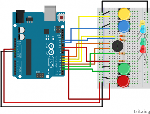
}Semáforo 3 led.
Realizar un montaje con tres leds (rojo, amarillo y verde) que haga la siguiente secuencia:
-
led rojo durante 800 ms
-
led amarillo parpadeo 4 veces 200 ms cada vez
-
led verde durante 500 ms
Nota: el cable rojo de 5V no se utiliza.
Para realizar el parpadeo utilizar el bloque repetitivo for.
Código Arduino
int led_rojo = 9;
int led_amarillo = 10;
int led_verde = 11;

void setup()
{
  pinMode(led_rojo, OUTPUT);
  pinMode(led_amarillo, OUTPUT);
  pinMode(led_verde, OUTPUT);
}

void loop()
{
  digitalWrite(led_rojo, HIGH);
  digitalWrite(led_amarillo, LOW);
  digitalWrite(led_verde, LOW);
  delay(800);

  digitalWrite(led_rojo, LOW);
  for(int i=0;i<4;i++){
    digitalWrite(led_amarillo, HIGH);
    delay(200);
    digitalWrite(led_amarillo, LOW);
    delay(200);
  }

  digitalWrite(led_verde, HIGH);
  delay(500);
}
2.2.-Entrada digital.
Se introducirán conceptos como:
-
Funciones digitales: digitalRead()
-
Función comunicación serie: Serial.begin(), Serial.println()
-
Estructuras condicionales: if y switch
-
Componentes:
-
Pulsador
-
-
Ampliación:
-
Resistencias Pull up y pull down.
-
Efecto rebote de los pulsadores
-
Para estos montajes necesitaremos:
-
Ordenador con IDE Arduino instalado.
-
Placa Arduino y cable USB.
-
Protoboard y cables de interconexión.
-
Leds y sus correspondientes resistencias de protección.
-
Pulsadores. No son necesarias resistencia Pull-down/up si usamos las resistencias internas de la placa Arduino.
Pulsador sin estado (led y pulsador)
Realizar un montaje con un led y un pulsador de modo que mientras se tenga presionado el pulsador el led esté encendido. Se necesitará crear un bloque condicional if para comprobar si el pulsador está presionado.
Como ampliación se puede realizar lo contrario, que el pulsador esté siempre enciendido y que solo se apague cuando se presione el pulsador.
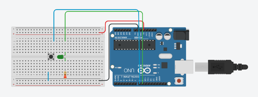
Nota: el cable rojo de 5V no se utiliza.
Código Arduino
int pulsador = 8;
int led = 9;

void setup() {
  pinMode(pulsador, INPUT_PULLUP); //Uso de la resistencia de pull-up interna
  pinMode(led, OUTPUT);
}

void loop() {
  int botonPulsado;

  botonPulsado = digitalRead(pulsador);

  if (botonPulsado == LOW)
  {
    digitalWrite(led, HIGH);
  }
  else
  {
    digitalWrite(led, LOW);
  }
}
|
Ampliación: Led con funcionamiento inverso al anterior. Siempre encendido y que se apague cuando se presione el pulsador. |
Código Arduino
int pulsador = 8;
int led = 9;

void setup() {
  pinMode(pulsador, INPUT_PULLUP); //Uso de la resistencia de pull-up interna
  pinMode(led, OUTPUT);
}

void loop() {
  int botonPulsado;

  botonPulsado = digitalRead(pulsador);

  if (botonPulsado == LOW)
  {
    digitalWrite(led, LOW); // si se pulsa -> apagar
  }
  else
  {
    digitalWrite(led, HIGH); // si no está pulsado -> encender
  }
}
Semáforo con pulsador.
Realizar un montaje con tres leds (rojo, amarillo y verde) y un pulsador de modo que simule un semáforo. Al principio el semáforo estará en rojo de forma constante. Cuando se presione el pulsador el led rojo se apagará, el led amarillo deberá parpadear 4 veces, se apagará y por último se volverá al estado inicial con el led rojo encindido de forma constante.
Nota: el cable rojo de 5V no se utiliza.
Código Arduino
int pulsador = 8;
int led_rojo = 9;
int led_amarillo = 10;
int led_verde = 11;

void setup()
{
  pinMode(pulsador, INPUT_PULLUP); //Uso de la resistencia de pull-up interna
  pinMode(led_rojo, OUTPUT);
  pinMode(led_amarillo, OUTPUT);
  pinMode(led_verde, OUTPUT);
}

void loop()
{
  int botonPulsado;

  botonPulsado = digitalRead(pulsador);

  if (botonPulsado == LOW)
  {
    digitalWrite(led_rojo, LOW);
    for (int i = 0; i < 4; i++) {
      digitalWrite(led_amarillo, HIGH);
      delay(200);
      digitalWrite(led_amarillo, LOW);
      delay(200);
    }
    digitalWrite(led_verde, HIGH);
    delay(500);
  }
  else
  {
    digitalWrite(led_rojo, HIGH);
    digitalWrite(led_amarillo, LOW);
    digitalWrite(led_verde, LOW);
  }
}
Dado aleatorio.
Realizar un montaje con cinco leds y un pulsador de modo que cada vez que se pulse se iluminen una cantidad aleatoria de leds ordenados. Es decir, si el valor aleatorio es 3 se iluminarán los tres primeros leds. Para el valor aleatorio usar la función ramdon(). El valor generado deberá estar entre 1 y 5 (el número de led)
Nota: el cable rojo de 5V no se utiliza.
|
Muestra el número generado por el monitor serie con la función Serial.println() para ir comprobando que tu montaje funciona correctamente. Prueba también la salida gráfica del monitor serie usando el Serial plotter. |
Código Arduino
// Propuesto|
Ampliación: Modifica el código para que en lugar de generar el número de forma aleatoria se pueda introducir por teclado. Utiliza el monitor serie con las funciones Serial.available() y Serial.parseInt() para enviarle el número a Arduino. |
Código Arduino
// Propuesto|
Ampliación: Modifica el código para utilizar un bloque switch en lugar de varios if. |
Código Arduino
// PropuestoPulsador con dos estado (on, off)
Reutilizando uno de los montajes anteriores de un led y un pulsador hacer que el led conserve su estado hasta la siguiente pulsación. Es decir si se presiona una vez el pulsador se enciende y si se vuelve a presionar se apaga. De modo que no hay que tener siempre el pulsador presionado. Para realizar esto debe existir una variable que almacene el estado del led. Esta variable habrá que comprobarla (if) para establecer si se enciende o se apaga el led.
|
Uso del operador lógico not (!). |
Código Arduino
int pulsador = 8;
int led = 9;
boolean estado=true; //2 posibles estados (true-false)

void setup() {
  pinMode(pulsador, INPUT_PULLUP); //Uso de la resistencia de pull-up interna
  pinMode(led, OUTPUT);
}

void loop() {
  int botonPulsado;

  botonPulsado = digitalRead(pulsador);

  if (botonPulsado == LOW)
  {
    estado=!estado; //estado opuesto del anterior
  }

  if (estado == true)
  {
    digitalWrite(led, HIGH);
  }
  else
  {
    digitalWrite(led, LOW);
  }
}
Pulsador con tres estado (off, blink, on). Contador y resto
Seguimos reutilizando el montaje anterior de un led y un pulsador. Ahora en lugar de dos estados (encendido y apagado) tiene que haber tres estados (encendido, parpadeando y apagado)
|
Uso de un contador ilimitado y la operación resto. |
Código Arduino
int pulsador = 8;
int led = 9;

void setup() {
  pinMode(pulsador, INPUT_PULLUP); //Uso de la resistencia de pull-up interna
  pinMode(led, OUTPUT);
}

void loop() {
  int botonPulsado;
  int estado=0; // Muchos estados posibles (cualquier número entero)
                // En nuestro ejemplo 3 (0,1,2)

  botonPulsado = digitalRead(pulsador);

  if (botonPulsado == LOW)
  {
    estado=estado+1;
    if(estado>2)
    {
      estado=0;
    }
  }

  if (estado == 0)
  {
    digitalWrite(led, LOW);
  }
  if (estado == 1)
  {
    digitalWrite(led, HIGH);
    delay(100);
    digitalWrite(led, LOW);
    delay(100);
  }
  if (estado == 2)
  {
    digitalWrite(led, HIGH);
  }

}
Código Arduino con contador ilimitado y operación resto
int pulsador = 8;
int led = 9;

void setup() {
  pinMode(pulsador, INPUT_PULLUP); //Uso de la resistencia de pull-up interna
  pinMode(led, OUTPUT);
}

void loop() {
  int botonPulsado;
  int estado=0; // Muchos estados posibles (cualquier número entero)
                // En nuestro ejemplo 3 (0,1,2)

  botonPulsado = digitalRead(pulsador);

  if (botonPulsado == LOW)
  {
    estado++; //estado=estado+1;
  }

  // estado%3 resto de dividir entre 3 (0, 1 o 2)
  if ((estado%3) == 0)
  {
    digitalWrite(led, LOW);
  }
  if ((estado%3) == 1)
  {
    digitalWrite(led, HIGH);
    delay(100);
    digitalWrite(led, LOW);
    delay(100);
  }
  if ((estado%3) == 2)
  {
    digitalWrite(led, HIGH);
  }

}
Código Arduino con bloque switch
int pulsador = 8;
int led = 9;

void setup() {
  pinMode(pulsador, INPUT_PULLUP); //Uso de la resistencia de pull-up interna
  pinMode(led, OUTPUT);
}

void loop() {
  int botonPulsado;
  int estado = 0; // Muchos estados posibles (cualquier número entero)
                  // En nuestro ejemplo 3 (0,1,2)

  botonPulsado = digitalRead(pulsador);

  if (botonPulsado == LOW)
  {
    estado++; //estado=estado+1;
  }

  // estado%3 resto de dividir entre 3 (0, 1 o 2)
  switch (estado % 3)
  {
    case 0:
      digitalWrite(led, LOW);
      break;
    case 1:
      digitalWrite(led, HIGH);
      delay(100);
      digitalWrite(led, LOW);
      delay(100);
      break;
    case 2:
      digitalWrite(led, LOW);
      break;
    default:
      break;
  }


}
Contador binario 2bit
Realizar un montaje con dos leds y un pulsador que simule un contador de números binarios de 0 a 3, es decir: 00, 01, 10, 11 Cada vez que se presione el pulsador se pasará al siguiente número, al llegar al último se volverá al principio.
|
Para más de dos estados se debe utilizar el bloque switch en lugar del bloque if. |
|
Muestra el número por el monitor serie con la función Serial.println() para ir comprobando que tu montaje funciona correctamente. |
Código Arduino
int pulsador = 8;
int led_uni = 3;
int led_dec = 4;

void setup() {
  pinMode(pulsador, INPUT_PULLUP);
  pinMode(led_uni, OUTPUT);
  pinMode(led_dec, OUTPUT);

  Serial.begin(9600);
}

void loop() {
  int botonPulsado;
  int estado = 0;

  botonPulsado = digitalRead(pulsador);

  if (botonPulsado == LOW)
  {
    estado++;
    Serial.println(estado);
  }


  // estado%4 resto de dividir entre 4 (0, 1, 2 o 3)
  switch (estado % 4)
  {
    case 0:
      digitalWrite(led_uni, LOW); // 00
      digitalWrite(led_dec, LOW);
      break;
    case 1:
      digitalWrite(led_uni, HIGH); // 01
      digitalWrite(led_dec, LOW);
      break;
    case 2:
      digitalWrite(led_uni, LOW); // 10
      digitalWrite(led_dec, HIGH);
      break;
    case 3:
      digitalWrite(led_uni, HIGH); // 11
      digitalWrite(led_dec, HIGH);
      break;
    default:
      break;
  }

}|
Ampliación: mismo montaje pero con dos pulsadores, uno para que incremente y otro para que decremente el número binario. |
Código Arduino
// Propuesto2.3.- Salida pseudo-analógica
Se introducirán conceptos como:
-
Resolución analógico-digital: 8 bits
-
Modulación por ancho de pulso (PWM)
-
Funciones analógicas: analogWrite(), tone(), notone()
-
Componentes básicos:
-
Led RGB
-
Buzzer
-
Para estos montajes necesitaremos:
-
Ordenador con IDE Arduino instalado.
-
Placa Arduino y cable USB.
-
Protoboard y cables de interconexión.
-
Led RGB
-
Buzzer
Cambio del brillo de un Led
Realizar un montaje con un led en un pin PWM que varía su brillo de 0 a 250 en saltos de 50 (0, 50, 100, …, 250) y una pausa de 200ms.
Código Arduino
int led = 5;

void setup() {
  pinMode(led, OUTPUT);
  Serial.begin(9600);
}

void loop() {

    analogWrite(led, 0);
    Serial.println("Brillo: 0");
    delay(200);

    analogWrite(led, 50);
    Serial.println("Brillo: 50");
    delay(200);

    analogWrite(led, 100);
    Serial.println("Brillo: 100");
    delay(200);

    analogWrite(led, 150);
    Serial.println("Brillo: 150");
    delay(200);

    analogWrite(led, 200);
    Serial.println("Brillo: 200");
    delay(200);

    analogWrite(led, 255);
    Serial.println("Brillo: 250");
    delay(200);
  }

}|
Ampliación: Modifica el código para hacerlo con un bucle for. |
Código Arduino
int led_verde = 5;
int led_rojo = 6;

void setup() {
  pinMode(led_verde, OUTPUT);
  pinMode(led_rojo, OUTPUT);
  Serial.begin(9600);
}

void loop() {
  for (int i = 0 ;  i < 255 ;  i++) {

    analogWrite(led_verde, i);
    analogWrite(led_rojo, 255 - i);
    Serial.println(i);
    delay(20);
  }

}
Led RGB (Red-Green-Blue)
Realicar un montaje con un led RGB conectado a 3 pines PWM que cambie a los siguientes colores. Recuerda hacer una pausa de 200ms entre cada color.
-
Rojo: 255, 0, 0
-
Naranja: 255, 128, 0
-
Amarillo: 255, 255, 0
-
Verde: 0, 255, 0
-
Azul: 0, 0, 255
-
Morado: 128, 0, 255
-
Rosa: 255, 0, 128
Código Arduino
int pinR = 9;
int pinG = 10;
int pinB = 11;

void setup()
{
  pinMode(pinR, OUTPUT);
  pinMode(pinG, OUTPUT);
  pinMode(pinB, OUTPUT);
  Serial.begin(9600);
}

void loop()
{
  analogWrite(pinR, 255);
  analogWrite(pinG, 0);
  analogWrite(pinB, 0);
  Serial.println("Rojo (255, 0, 0) ");
  delay(200);

  analogWrite(pinR, 255);
  analogWrite(pinG, 128);
  analogWrite(pinB, 0);
  Serial.println("Naranja (255, 128, 0) ");
  delay(200);

  analogWrite(pinR, 255);
  analogWrite(pinG, 255);
  analogWrite(pinB, 0);
  Serial.println("Amarillo (255, 255, 0) ");
  delay(200);

  analogWrite(pinR, 0);
  analogWrite(pinG, 255);
  analogWrite(pinB, 0);
  Serial.println("Verde (0, 255, 0) ");
  delay(200);

  analogWrite(pinR, 0);
  analogWrite(pinG, 0);
  analogWrite(pinB, 255);
  Serial.println("Azul (0, 0, 255) ");
  delay(200);


  analogWrite(pinR, 128);
  analogWrite(pinG, 0);
  analogWrite(pinB, 255);
  Serial.println("Morado (128, 0, 255) ");
  delay(200);


  analogWrite(pinR, 255);
  analogWrite(pinG, 0);
  analogWrite(pinB, 128);
  Serial.println("Rosa (255, 0, 128) ");
  delay(200);
}|
Ampliación: Modifica el código para hacerlo con un bucle for. |
Código Arduino
int pinR = 9;
int pinG = 10;
int pinB = 11;

void setup()
{
  pinMode(pinR, OUTPUT);
  pinMode(pinG, OUTPUT);
  pinMode(pinB, OUTPUT);
  Serial.begin(9600);
}

void loop()
{
  for (int i = 0; i < 255; i++)
  {
    for (int j = 0; j < 255; j++)
    {
      for (int k = 0; k < 255; k++)
      {
        analogWrite(pinR, i);
        analogWrite(pinG, j);
        analogWrite(pinB, k);
        Serial.print(i);
        Serial.print(", ");
        Serial.print(j);
        Serial.print(", ");
        Serial.println(k);
        delay(20);
      }
    }
  }
}
Buzzer
Buzzer: sonidos básicos
Realizar un montaje con un buzzer pasivo que genere tonos desde 250Hz a 350Hz de 25 en 25. Los tonos tendrán una duración de 200ms.
Código Arduino
const int pulsador=2;
const int buzz=4;

int estado=0;

void setup(){
  pinMode(buzz,OUTPUT);
  pinMode(pulsador,INPUT_PULLUP);
}

void loop(){

  estado = digitalRead(pulsador);
  if(estado==LOW){
    tone(buzz,250,200);
    delay(400);
    tone(buzz,275,200);
    delay(400);
    tone(buzz,300,200);
    delay(400);
    tone(buzz,325,200);
    delay(400);
    tone(buzz,350,200);
    delay(400);
  }
  noTone(buzz);
}|
Ampliación: Modifica el código para hacerlo con un bucle for. |
Código Arduino
const int pulsador = 2;
const int buzz = 4;

int estado = 0;

void setup()
{
  pinMode(buzz, OUTPUT);
  pinMode(pulsador, INPUT_PULLUP);
}

void loop()
{

  estado = digitalRead(pulsador);
  if (estado == LOW)
  {
    for (int i = 250; i < 350; i = i + 25)
    {
      tone(buzz, i, 200);
    }
  }
  noTone(buzz);
}
Buzzer: Piano
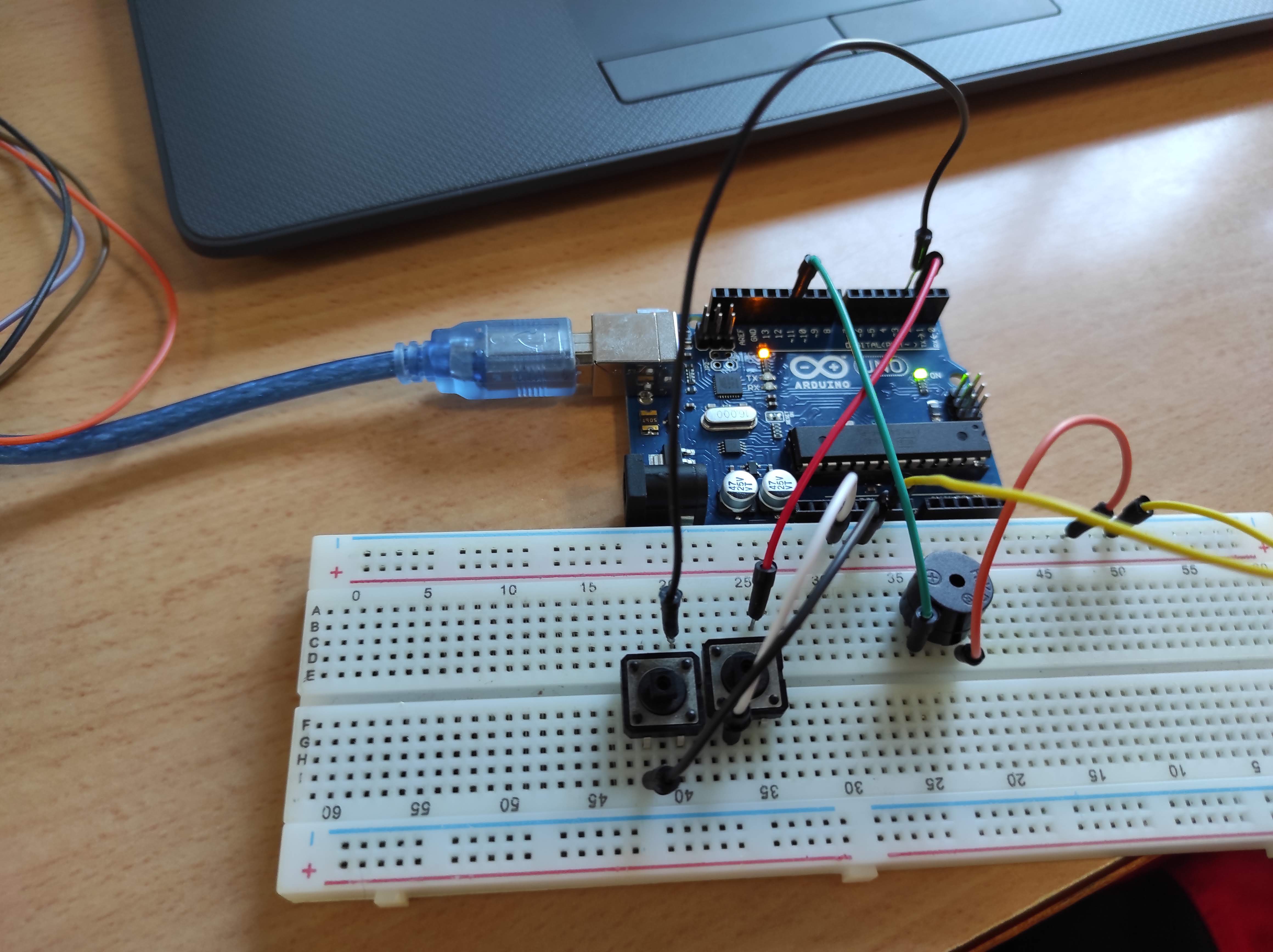
Realizar un montaje con un buzzer pasivo y tres pulsadores. Cada pulsador hará sonar una nota musical: Do (262Hz), Re (294Hz) y Mi (330).
Código Arduino
const int buzz = 11;

const int doPin =2;
const int rePin =3;
const int miPin =4;

const int DO  = 262;
const int RE  = 294;
const int MI  = 330;


// Configuración

void setup(){
  pinMode(buzz, OUTPUT);
}

// Programa

void loop(){

  while(digitalRead(doPin) == HIGH){
    tone(buzz, DO);
  }
  while(digitalRead(rePin) == HIGH){
    tone(buzz, RE);
  }
  while(digitalRead(miPin) == HIGH){
    tone(buzz, MI);
  }
  noTone(buzz);

}|
Ampliación: Usa más pulsadores y completa la escala musical. |
Buzzer: melodías
Realizar un montaje con un buzzer pasivo que genere tonos desde 250Hz a 350Hz de 25 en 25. Los tonos tendrán una duración de 200ms.
Código Arduino
/**
 * La Guerra de las Galaxias
 */

static int PIN_BUZZER = 9;

int c[5]={131,262,523,1046,2093}; // Do
int d[5]={147,294,587,1175,2349}; // Re
int e[5]={165,330,659,1319,2637}; // Mi
int f[5]={175,349,698,1397,2794}; // Fa
int g[5]={196,392,784,1568,3136}; // Sol
int a[5]={220,440,880,1760,3520}; // La
int b[5]={247,494,988,1976,3951}; // Si

void nota(int frecuencia, int duracion)
{
  tone(PIN_BUZZER, frecuencia);
  delay(duracion);
  noTone(PIN_BUZZER);
  delay(50);
}

void setup() {

}

void loop() {
  nota(f[2],500);
  nota(f[2],500);
  nota(f[2],500);
  nota(d[2],250);//
  nota(a[2],250);
  nota(f[2],500);
  nota(d[2],250);//
  nota(a[2],250);
  nota(f[2],500);
  delay(500);
  nota(c[3],500);
  nota(c[3],500);
  nota(c[3],500);
  nota(d[3],250);
  nota(a[2],250);
  nota(f[2],500);
  nota(d[2],250);//
  nota(a[2],250);
  nota(f[2],500);
  delay(1000);
}|
Ampliación: busca en la siguiente web otras melodías y pruebalas. |
2.4.- Entrada analógica.
Se introducirán conceptos como:
-
Resolución analógico-digital: 10 bits
-
Funciones analógicas: analogRead()
-
Función de reescalado: map()
-
Salida gráfica de comunicación serie. Plotter Serial
-
Componentes básicos:
-
Potenciometro
-
Joystick
-
LDR y resistencia pull-down/up
-
DHT11
-
Para estos montajes necesitaremos:
-
Ordenador con IDE Arduino instalado.
-
Placa Arduino y cable USB.
-
Protoboard y cables de interconexión.
-
Resistencias variables (potenciometro y joystick)
Potenciometro y Serial
Código Arduino
Joystick y Serial
Código Arduino
{Ampliación} LDR y Serial
Código Arduino
const int ldr = A0;


void setup() {
  Serial.begin(9600);
  pinMode(ldr, INPUT); //No hace falta
}

void loop() {
  int valor_ldr = analogRead(ldr); //0-1023
  Serial.println(valor_ldr);

}
2.5.- Entrada y salida analógica
Potenciometro y leds
Código Arduino
, /*
	Potenciometro en A0 (2^10 bits)
	3 led en 9, 10 y 11 (todos PWM. 2^8 bits)
*/

const int pot = A0;

const int led1 = 11;
const int led2 = 10;
const int led3 = 9;

void setup() {
  Serial.begin(9600);
  pinMode(pot, INPUT); //No hace falta
  pinMode(led1, OUTPUT);
  pinMode(led2, OUTPUT);
  pinMode(led3, OUTPUT);
}

void loop() {
  int valor_pot = analogRead(pot); // 0-1023
  //Serial.println(valor_pot);
  int valor_escalado = map(valor_pot, 0, 1023, 0, 255);
  //Serial.println(valor_escalado); // 0-255

  analogWrite(led1, valor_escalado);
  analogWrite(led2, 255-valor_escalado);
  analogWrite(led3, valor_escalado);
}
Joystick y leds
Código Arduino
const int joyX = A0;
const int joyY = A1;
const int led1 = 11;
const int led2 = 10;

void setup() {
  Serial.begin(9600);
  pinMode(joyX, INPUT); //No hace falta
  pinMode(joyY, INPUT); //No hace falta
  pinMode(led1, OUTPUT);
  pinMode(led2, OUTPUT);
}

void loop() {
  int valor_X = analogRead(joyX); //0-1023
  int valor_Y = analogRead(joyY); //0-1023
  Serial.println(valor_X);
  Serial.println(valor_Y);

  int valor_escaladoX = map(valor_X, 0, 1023, 0, 255);
  int valor_escaladoY = map(valor_Y, 0, 1023, 0, 255);
  //Serial.println(valor_escalado); // 0-255

  analogWrite(led1, valor_escaladoX);
  analogWrite(led2, valor_escaladoY);
}
Joystick y led RGB
Código Arduino
int R 3;
int G 5;
int B 6;
int angulo_X = 0;
int angulo_Y = 0;
int eje_X = A0;
int eje_Y = A1;


void setup() {
 pinMode(R, OUTPUT);
 pinMode(G, OUTPUT);
 pinMode(B, OUTPUT);
 pinMode(eje_X,INPUT);
 pinMode(eje_Y,INPUT);
 Serial.begin(9600);
}

void loop() {

 int valor_pot1 =  analogRead(eje_X);
 int valor_escalado1 = map(valor_pot1 , 0, 1023, 0, 255);
 Serial.println(valor_escalado1);

 int valor_pot2 =  analogRead(eje_Y);
 int valor_escalado2 = map(valor_pot2 , 0, 1023, 0, 255);
 Serial.println(valor_escalado2);

 analogWrite(G, valor_escalado1);
 analogWrite(B, valor_escalado2);
 analogWrite(R, 150);
}|
Ampliación: Con un joystick y un potenciometro puedes controlar los tres colores del led RGB. |
Simon says
Código Arduino
/*
 SparkFun Inventor's Kit
 Example sketch 16
 Spark Fun Electronics
 Oct. 7, 2014
 https://learn.sparkfun.com/tutorials/sik-experiment-guide-for-arduino---v32/experiment-16-simon-says

 Simon Says is a memory game. Start the game by pressing one of the four buttons. When a button lights up,
 press the button, repeating the sequence. The sequence will get longer and longer. The game is won after
 13 rounds.

 Generates random sequence, plays music, and displays button lights.

 Simon tones from Wikipedia
 - A (red, upper left) - 440Hz - 2.272ms - 1.136ms pulse
 - a (green, upper right, an octave higher than A) - 880Hz - 1.136ms,
 0.568ms pulse
 - D (blue, lower left, a perfect fourth higher than the upper left)
 587.33Hz - 1.702ms - 0.851ms pulse
 - G (yellow, lower right, a perfect fourth higher than the lower left) -
 784Hz - 1.276ms - 0.638ms pulse

 Simon Says game originally written in C for the PIC16F88.
 Ported for the ATmega168, then ATmega328, then Arduino 1.0.
 Fixes and cleanup by Joshua Neal <joshua[at]trochotron.com>

 This sketch was written by SparkFun Electronics,
 with lots of help from the Arduino community.
 This code is completely free for any use.
 Visit http://www.arduino.cc to learn about the Arduino.
 */

/*************************************************
* Public Constants
*************************************************/
// Led pin definitions
#define LED_RED     10
#define LED_GREEN   3
#define LED_BLUE    13
#define LED_YELLOW  5

// Button pin definitions
#define BUTTON_RED    9
#define BUTTON_GREEN  2
#define BUTTON_BLUE   12
#define BUTTON_YELLOW 6

// Buzzer pin definitions
#define BUZZER1  4
#define BUZZER2  7

#define NOTE_B0 31
#define NOTE_C1 33
#define NOTE_CS1 35
#define NOTE_D1 37
#define NOTE_DS1 39
#define NOTE_E1 41
#define NOTE_F1 44
#define NOTE_FS1 46
#define NOTE_G1 49
#define NOTE_GS1 52
#define NOTE_A1 55
#define NOTE_AS1 58
#define NOTE_B1 62
#define NOTE_C2 65
#define NOTE_CS2 69
#define NOTE_D2 73
#define NOTE_DS2 78
#define NOTE_E2 82
#define NOTE_F2 87
#define NOTE_FS2 93
#define NOTE_G2 98
#define NOTE_GS2 104
#define NOTE_A2 110
#define NOTE_AS2 117
#define NOTE_B2 123
#define NOTE_C3 131
#define NOTE_CS3 139
#define NOTE_D3 147
#define NOTE_DS3 156
#define NOTE_E3 165
#define NOTE_F3 175
#define NOTE_FS3 185
#define NOTE_G3 196
#define NOTE_GS3 208
#define NOTE_A3 220
#define NOTE_AS3 233
#define NOTE_B3 247
#define NOTE_C4 262
#define NOTE_CS4 277
#define NOTE_D4 294
#define NOTE_DS4 311
#define NOTE_E4 330
#define NOTE_F4 349
#define NOTE_FS4 370
#define NOTE_G4 392
#define NOTE_GS4 415
#define NOTE_A4 440
#define NOTE_AS4 466
#define NOTE_B4 494
#define NOTE_C5 523
#define NOTE_CS5 554
#define NOTE_D5 587
#define NOTE_DS5 622
#define NOTE_E5 659
#define NOTE_F5 698
#define NOTE_FS5 740
#define NOTE_G5 784
#define NOTE_GS5 831
#define NOTE_A5 880
#define NOTE_AS5 932
#define NOTE_B5 988
#define NOTE_C6 1047
#define NOTE_CS6 1109
#define NOTE_D6 1175
#define NOTE_DS6 1245
#define NOTE_E6 1319
#define NOTE_F6 1397
#define NOTE_FS6 1480
#define NOTE_G6 1568
#define NOTE_GS6 1661
#define NOTE_A6 1760
#define NOTE_AS6 1865
#define NOTE_B6 1976
#define NOTE_C7 2093
#define NOTE_CS7 2217
#define NOTE_D7 2349
#define NOTE_DS7 2489
#define NOTE_E7 2637
#define NOTE_F7 2794
#define NOTE_FS7 2960
#define NOTE_G7 3136
#define NOTE_GS7 3322
#define NOTE_A7 3520
#define NOTE_AS7 3729
#define NOTE_B7 3951
#define NOTE_C8 4186
#define NOTE_CS8 4435
#define NOTE_D8 4699
#define NOTE_DS8 4978

#define CHOICE_OFF      0 //Used to control LEDs
#define CHOICE_NONE     0 //Used to check buttons
#define CHOICE_RED  (1 << 0)
#define CHOICE_GREEN    (1 << 1)
#define CHOICE_BLUE (1 << 2)
#define CHOICE_YELLOW   (1 << 3)

// Define game parameters
#define ROUNDS_TO_WIN      13 //Number of rounds to succesfully remember before you win. 13 is do-able.
#define ENTRY_TIME_LIMIT   3000 //Amount of time to press a button before game times out. 3000ms = 3 sec

#define MODE_MEMORY  0
#define MODE_BATTLE  1
#define MODE_BEEGEES 2

// Game state variables
byte gameMode = MODE_MEMORY; //By default, let's play the memory game
byte gameBoard[32]; //Contains the combination of buttons as we advance
byte gameRound = 0; //Counts the number of succesful rounds the player has made it through

void setup()
{
  //Setup hardware inputs/outputs. These pins are defined in the hardware_versions header file

  //Enable pull ups on inputs
  pinMode(BUTTON_RED, INPUT_PULLUP);
  pinMode(BUTTON_GREEN, INPUT_PULLUP);
  pinMode(BUTTON_BLUE, INPUT_PULLUP);
  pinMode(BUTTON_YELLOW, INPUT_PULLUP);

  pinMode(LED_RED, OUTPUT);
  pinMode(LED_GREEN, OUTPUT);
  pinMode(LED_BLUE, OUTPUT);
  pinMode(LED_YELLOW, OUTPUT);

  pinMode(BUZZER1, OUTPUT);
  pinMode(BUZZER2, OUTPUT);

  //Mode checking
  gameMode = MODE_MEMORY; // By default, we're going to play the memory game

  // Check to see if the lower right button is pressed
  if (checkButton() == CHOICE_YELLOW) play_beegees();

  // Check to see if upper right button is pressed
  if (checkButton() == CHOICE_GREEN)
  {
    gameMode = MODE_BATTLE; //Put game into battle mode

    //Turn on the upper right (green) LED
    setLEDs(CHOICE_GREEN);
    toner(CHOICE_GREEN, 150);

    setLEDs(CHOICE_RED | CHOICE_BLUE | CHOICE_YELLOW); // Turn on the other LEDs until you release button

    while(checkButton() != CHOICE_NONE) ; // Wait for user to stop pressing button

    //Now do nothing. Battle mode will be serviced in the main routine
  }

  play_winner(); // After setup is complete, say hello to the world
}

void loop()
{
  attractMode(); // Blink lights while waiting for user to press a button

  // Indicate the start of game play
  setLEDs(CHOICE_RED | CHOICE_GREEN | CHOICE_BLUE | CHOICE_YELLOW); // Turn all LEDs on
  delay(1000);
  setLEDs(CHOICE_OFF); // Turn off LEDs
  delay(250);

  if (gameMode == MODE_MEMORY)
  {
    // Play memory game and handle result
    if (play_memory() == true)
      play_winner(); // Player won, play winner tones
    else
      play_loser(); // Player lost, play loser tones
  }

  if (gameMode == MODE_BATTLE)
  {
    play_battle(); // Play game until someone loses

    play_loser(); // Player lost, play loser tones
  }
}

//-=-=-=-=-=-=-=-=-=-=-=-=-=-=-=-=-=-=-=-=-=-=-=-=-=-=-=-=-=-=
//The following functions are related to game play only

// Play the regular memory game
// Returns 0 if player loses, or 1 if player wins
boolean play_memory(void)
{
  randomSeed(millis()); // Seed the random generator with random amount of millis()

  gameRound = 0; // Reset the game to the beginning

  while (gameRound < ROUNDS_TO_WIN)
  {
    add_to_moves(); // Add a button to the current moves, then play them back

    playMoves(); // Play back the current game board

    // Then require the player to repeat the sequence.
    for (byte currentMove = 0 ; currentMove < gameRound ; currentMove++)
    {
      byte choice = wait_for_button(); // See what button the user presses

      if (choice == 0) return false; // If wait timed out, player loses

      if (choice != gameBoard[currentMove]) return false; // If the choice is incorect, player loses
    }

    delay(1000); // Player was correct, delay before playing moves
  }

  return true; // Player made it through all the rounds to win!
}

// Play the special 2 player battle mode
// A player begins by pressing a button then handing it to the other player
// That player repeats the button and adds one, then passes back.
// This function returns when someone loses
boolean play_battle(void)
{
  gameRound = 0; // Reset the game frame back to one frame

  while (1) // Loop until someone fails
  {
    byte newButton = wait_for_button(); // Wait for user to input next move
    gameBoard[gameRound++] = newButton; // Add this new button to the game array

    // Then require the player to repeat the sequence.
    for (byte currentMove = 0 ; currentMove < gameRound ; currentMove++)
    {
      byte choice = wait_for_button();

      if (choice == 0) return false; // If wait timed out, player loses.

      if (choice != gameBoard[currentMove]) return false; // If the choice is incorect, player loses.
    }

    delay(100); // Give the user an extra 100ms to hand the game to the other player
  }

  return true; // We should never get here
}

// Plays the current contents of the game moves
void playMoves(void)
{
  for (byte currentMove = 0 ; currentMove < gameRound ; currentMove++)
  {
    toner(gameBoard[currentMove], 150);

    // Wait some amount of time between button playback
    // Shorten this to make game harder
    delay(150); // 150 works well. 75 gets fast.
  }
}

// Adds a new random button to the game sequence, by sampling the timer
void add_to_moves(void)
{
  byte newButton = random(0, 4); //min (included), max (exluded)

  // We have to convert this number, 0 to 3, to CHOICEs
  if(newButton == 0) newButton = CHOICE_RED;
  else if(newButton == 1) newButton = CHOICE_GREEN;
  else if(newButton == 2) newButton = CHOICE_BLUE;
  else if(newButton == 3) newButton = CHOICE_YELLOW;

  gameBoard[gameRound++] = newButton; // Add this new button to the game array
}

//-=-=-=-=-=-=-=-=-=-=-=-=-=-=-=-=-=-=-=-=-=-=-=-=-=-=-=-=-=-=
//The following functions control the hardware

// Lights a given LEDs
// Pass in a byte that is made up from CHOICE_RED, CHOICE_YELLOW, etc
void setLEDs(byte leds)
{
  if ((leds & CHOICE_RED) != 0)
    digitalWrite(LED_RED, HIGH);
  else
    digitalWrite(LED_RED, LOW);

  if ((leds & CHOICE_GREEN) != 0)
    digitalWrite(LED_GREEN, HIGH);
  else
    digitalWrite(LED_GREEN, LOW);

  if ((leds & CHOICE_BLUE) != 0)
    digitalWrite(LED_BLUE, HIGH);
  else
    digitalWrite(LED_BLUE, LOW);

  if ((leds & CHOICE_YELLOW) != 0)
    digitalWrite(LED_YELLOW, HIGH);
  else
    digitalWrite(LED_YELLOW, LOW);
}

// Wait for a button to be pressed.
// Returns one of LED colors (LED_RED, etc.) if successful, 0 if timed out
byte wait_for_button(void)
{
  long startTime = millis(); // Remember the time we started the this loop

  while ( (millis() - startTime) < ENTRY_TIME_LIMIT) // Loop until too much time has passed
  {
    byte button = checkButton();

    if (button != CHOICE_NONE)
    {
      toner(button, 150); // Play the button the user just pressed

      while(checkButton() != CHOICE_NONE) ;  // Now let's wait for user to release button

      delay(10); // This helps with debouncing and accidental double taps

      return button;
    }

  }

  return CHOICE_NONE; // If we get here, we've timed out!
}

// Returns a '1' bit in the position corresponding to CHOICE_RED, CHOICE_GREEN, etc.
byte checkButton(void)
{
  if (digitalRead(BUTTON_RED) == 0) return(CHOICE_RED);
  else if (digitalRead(BUTTON_GREEN) == 0) return(CHOICE_GREEN);
  else if (digitalRead(BUTTON_BLUE) == 0) return(CHOICE_BLUE);
  else if (digitalRead(BUTTON_YELLOW) == 0) return(CHOICE_YELLOW);

  return(CHOICE_NONE); // If no button is pressed, return none
}

// Light an LED and play tone
// Red, upper left:     440Hz - 2.272ms - 1.136ms pulse
// Green, upper right:  880Hz - 1.136ms - 0.568ms pulse
// Blue, lower left:    587.33Hz - 1.702ms - 0.851ms pulse
// Yellow, lower right: 784Hz - 1.276ms - 0.638ms pulse
void toner(byte which, int buzz_length_ms)
{
  setLEDs(which); //Turn on a given LED

  //Play the sound associated with the given LED
  switch(which)
  {
  case CHOICE_RED:
    buzz_sound(buzz_length_ms, 1136);
    break;
  case CHOICE_GREEN:
    buzz_sound(buzz_length_ms, 568);
    break;
  case CHOICE_BLUE:
    buzz_sound(buzz_length_ms, 851);
    break;
  case CHOICE_YELLOW:
    buzz_sound(buzz_length_ms, 638);
    break;
  }

  setLEDs(CHOICE_OFF); // Turn off all LEDs
}

// Toggle buzzer every buzz_delay_us, for a duration of buzz_length_ms.
void buzz_sound(int buzz_length_ms, int buzz_delay_us)
{
  // Convert total play time from milliseconds to microseconds
  long buzz_length_us = buzz_length_ms * (long)1000;

  // Loop until the remaining play time is less than a single buzz_delay_us
  while (buzz_length_us > (buzz_delay_us * 2))
  {
    buzz_length_us -= buzz_delay_us * 2; //Decrease the remaining play time

    // Toggle the buzzer at various speeds
    digitalWrite(BUZZER1, LOW);
    digitalWrite(BUZZER2, HIGH);
    delayMicroseconds(buzz_delay_us);

    digitalWrite(BUZZER1, HIGH);
    digitalWrite(BUZZER2, LOW);
    delayMicroseconds(buzz_delay_us);
  }
}

// Play the winner sound and lights
void play_winner(void)
{
  setLEDs(CHOICE_GREEN | CHOICE_BLUE);
  winner_sound();
  setLEDs(CHOICE_RED | CHOICE_YELLOW);
  winner_sound();
  setLEDs(CHOICE_GREEN | CHOICE_BLUE);
  winner_sound();
  setLEDs(CHOICE_RED | CHOICE_YELLOW);
  winner_sound();
}

// Play the winner sound
// This is just a unique (annoying) sound we came up with, there is no magic to it
void winner_sound(void)
{
  // Toggle the buzzer at various speeds
  for (byte x = 250 ; x > 70 ; x--)
  {
    for (byte y = 0 ; y < 3 ; y++)
    {
      digitalWrite(BUZZER2, HIGH);
      digitalWrite(BUZZER1, LOW);
      delayMicroseconds(x);

      digitalWrite(BUZZER2, LOW);
      digitalWrite(BUZZER1, HIGH);
      delayMicroseconds(x);
    }
  }
}

// Play the loser sound/lights
void play_loser(void)
{
  setLEDs(CHOICE_RED | CHOICE_GREEN);
  buzz_sound(255, 1500);

  setLEDs(CHOICE_BLUE | CHOICE_YELLOW);
  buzz_sound(255, 1500);

  setLEDs(CHOICE_RED | CHOICE_GREEN);
  buzz_sound(255, 1500);

  setLEDs(CHOICE_BLUE | CHOICE_YELLOW);
  buzz_sound(255, 1500);
}

// Show an "attract mode" display while waiting for user to press button.
void attractMode(void)
{
  while(1)
  {
    setLEDs(CHOICE_RED);
    delay(100);
    if (checkButton() != CHOICE_NONE) return;

    setLEDs(CHOICE_BLUE);
    delay(100);
    if (checkButton() != CHOICE_NONE) return;

    setLEDs(CHOICE_GREEN);
    delay(100);
    if (checkButton() != CHOICE_NONE) return;

    setLEDs(CHOICE_YELLOW);
    delay(100);
    if (checkButton() != CHOICE_NONE) return;
  }
}

//-=-=-=-=-=-=-=-=-=-=-=-=-=-=-=-=-=-=-=-=-=-=-=-=-=-=-=-=-=-=
// The following functions are related to Beegees Easter Egg only

// Notes in the melody. Each note is about an 1/8th note, "0"s are rests.
int melody[] = {
  NOTE_G4, NOTE_A4, 0, NOTE_C5, 0, 0, NOTE_G4, 0, 0, 0,
  NOTE_E4, 0, NOTE_D4, NOTE_E4, NOTE_G4, 0,
  NOTE_D4, NOTE_E4, 0, NOTE_G4, 0, 0,
  NOTE_D4, 0, NOTE_E4, 0, NOTE_G4, 0, NOTE_A4, 0, NOTE_C5, 0};

int noteDuration = 115; // This essentially sets the tempo, 115 is just about right for a disco groove :)
int LEDnumber = 0; // Keeps track of which LED we are on during the beegees loop

// Do nothing but play bad beegees music
// This function is activated when user holds bottom right button during power up
void play_beegees()
{
  //Turn on the bottom right (yellow) LED
  setLEDs(CHOICE_YELLOW);
  toner(CHOICE_YELLOW, 150);

  setLEDs(CHOICE_RED | CHOICE_GREEN | CHOICE_BLUE); // Turn on the other LEDs until you release button

  while(checkButton() != CHOICE_NONE) ; // Wait for user to stop pressing button

  setLEDs(CHOICE_NONE); // Turn off LEDs

  delay(1000); // Wait a second before playing song

  digitalWrite(BUZZER1, LOW); // setup the "BUZZER1" side of the buzzer to stay low, while we play the tone on the other pin.

  while(checkButton() == CHOICE_NONE) //Play song until you press a button
  {
    // iterate over the notes of the melody:
    for (int thisNote = 0; thisNote < 32; thisNote++) {
      changeLED();
      tone(BUZZER2, melody[thisNote],noteDuration);
      // to distinguish the notes, set a minimum time between them.
      // the note's duration + 30% seems to work well:
      int pauseBetweenNotes = noteDuration * 1.30;
      delay(pauseBetweenNotes);
      // stop the tone playing:
      noTone(BUZZER2);
    }
  }
}

// Each time this function is called the board moves to the next LED
void changeLED(void)
{
  setLEDs(1 << LEDnumber); // Change the LED

  LEDnumber++; // Goto the next LED
  if(LEDnumber > 3) LEDnumber = 0; // Wrap the counter if needed
}
Montajes avanzados. Uso de librerías.
Una vez que se conozcan las estructuras básicas de programación y los componentes electronicos más simples podremos plantear montajes que utilicen librerías para su desarrollo. Cada nuevo componente electrónico requerirá de una explicación de su funcionamiento físico y de sus librerías de programación.
Se introducirán conceptos como:
-
Uso de librerías. Importar
-
Componentes básicos:
-
Servomotor
-
Ultrasonicos
-
Potenciometro y servomotor
Código Arduino
#include <Servo.h>

int pot = A0;
int pinServo = 6;

Servo servoMotor;

int valor;

void setup()
{
    pinMode(pot,INPUT);
    servoMotor.attach(pinServo);
    Serial.begin(9600);
}

void loop() {
    valor =  analogRead(pot);
    valor = map(valor, 0, 1023, 0, 180);
    servoMotor.write(valor);
    //Serial.println(valor);
}
Joystick y servomotor
Código Arduino
#include <Servo.h>

int joyEjeX = A0;
int pinServo = 6;

Servo servoMotor;

int valor;

void setup()
{
    pinMode(joyEjeX,INPUT);
    servoMotor.attach(pinServo);
    Serial.begin(9600);
}

void loop() {
    valor =  analogRead(joyEjeX);
    valor = map(valor, 0, 1023, 0, 180);
    servoMotor.write(valor);
    //Serial.println(valor);
}|
Ampliación: Añade un segundo servomotor para controlar ambos con un sólo joystick. 
|
Código Arduino
#include <Servo.h>

int joyEjeX = A0;
int joyEjeY = A1;
int pinServo1 = 5;
int pinServo2 = 6;

Servo servoMotor1;
Servo servoMotor2;

int valorX;
int valorY;

void setup()
{
    pinMode(joyEjeX,INPUT);
    pinMode(joyEjeY,INPUT);
    servoMotor1.attach(pinServo1);
    servoMotor2.attach(pinServo2);
    Serial.begin(9600);
}

void loop() {
    valorX =  analogRead(joyEjeX);
    valorY =  analogRead(joyEjeY);
    valorX = map(valorX, 0, 1023, 0, 180);
    valorY = map(valorY, 0, 1023, 0, 180);
    servoMotor.write(valorX);
    servoMotor.write(valorY);
    //Serial.print(valorX);
    //Serial.print(":");
    //Serial.println(valorY);
}
Ultrasonidos y servomotor
Código Arduino
#include <Servo.h>

const int EchoPin = 12;
const int TriggerPin = 11;

Servo servoMotor;

void setup()
{
  pinMode(TriggerPin, OUTPUT);
  pinMode(EchoPin, INPUT);
  servoMotor.attach(6);
}

void loop() {

  int cm = ping(TriggerPin, EchoPin);
  Serial.print("Distancia: ");
  Serial.println(cm);
  delay(1000);
  if (cm > 50)
  {
    cm = 50;
  }

  if (cm < 0)
  {
    cm = 0;
  }
  int valor_escalado = map(cm , 0, 50, 0, 180);
  servoMotor.write(valor_escalado);
  //Serial.print("Ángulo: ");
  //Serial.println(valor_escalado);
  delay(1000);
}

int ping(int TriggerPin, int EchoPin) {
  long duration, distanceCm;

  digitalWrite(TriggerPin, LOW);
  delayMicroseconds(4);
  digitalWrite(TriggerPin, HIGH);
  delayMicroseconds(10);
  digitalWrite(TriggerPin, LOW);

  duration = pulseIn(EchoPin, HIGH);

  distanceCm = duration * 10 / 292 / 2;


  return distanceCm;
}
Jumping game
Código Arduino
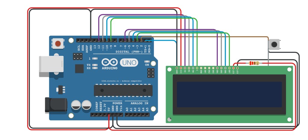
#include <LiquidCrystal.h>

#define PIN_BUTTON 2
#define PIN_AUTOPLAY 1
#define PIN_READWRITE 10
#define PIN_CONTRAST 12

#define SPRITE_RUN1 1
#define SPRITE_RUN2 2
#define SPRITE_JUMP 3
#define SPRITE_JUMP_UPPER '.'         // Use the '.' character for the head
#define SPRITE_JUMP_LOWER 4
#define SPRITE_TERRAIN_EMPTY ' '      // User the ' ' character
#define SPRITE_TERRAIN_SOLID 5
#define SPRITE_TERRAIN_SOLID_RIGHT 6
#define SPRITE_TERRAIN_SOLID_LEFT 7

#define HERO_HORIZONTAL_POSITION 1    // Horizontal position of hero on screen

#define TERRAIN_WIDTH 16
#define TERRAIN_EMPTY 0
#define TERRAIN_LOWER_BLOCK 1
#define TERRAIN_UPPER_BLOCK 2

#define HERO_POSITION_OFF 0          // Hero is invisible
#define HERO_POSITION_RUN_LOWER_1 1  // Hero is running on lower row (pose 1)
#define HERO_POSITION_RUN_LOWER_2 2  //                              (pose 2)

#define HERO_POSITION_JUMP_1 3       // Starting a jump
#define HERO_POSITION_JUMP_2 4       // Half-way up
#define HERO_POSITION_JUMP_3 5       // Jump is on upper row
#define HERO_POSITION_JUMP_4 6       // Jump is on upper row
#define HERO_POSITION_JUMP_5 7       // Jump is on upper row
#define HERO_POSITION_JUMP_6 8       // Jump is on upper row
#define HERO_POSITION_JUMP_7 9       // Half-way down
#define HERO_POSITION_JUMP_8 10      // About to land

#define HERO_POSITION_RUN_UPPER_1 11 // Hero is running on upper row (pose 1)
#define HERO_POSITION_RUN_UPPER_2 12 //                              (pose 2)

LiquidCrystal lcd(11, 9, 6, 5, 4, 3);
static char terrainUpper[TERRAIN_WIDTH + 1];
static char terrainLower[TERRAIN_WIDTH + 1];
static bool buttonPushed = false;

void initializeGraphics() {
  static byte graphics[] = {
    // Run position 1
    B01100,
    B01100,
    B00000,
    B01110,
    B11100,
    B01100,
    B11010,
    B10011,
    // Run position 2
    B01100,
    B01100,
    B00000,
    B01100,
    B01100,
    B01100,
    B01100,
    B01110,
    // Jump
    B01100,
    B01100,
    B00000,
    B11110,
    B01101,
    B11111,
    B10000,
    B00000,
    // Jump lower
    B11110,
    B01101,
    B11111,
    B10000,
    B00000,
    B00000,
    B00000,
    B00000,
    // Ground
    B11111,
    B11111,
    B11111,
    B11111,
    B11111,
    B11111,
    B11111,
    B11111,
    // Ground right
    B00011,
    B00011,
    B00011,
    B00011,
    B00011,
    B00011,
    B00011,
    B00011,
    // Ground left
    B11000,
    B11000,
    B11000,
    B11000,
    B11000,
    B11000,
    B11000,
    B11000,
  };
  int i;
  // Skip using character 0, this allows lcd.print() to be used to
  // quickly draw multiple characters
  for (i = 0; i < 7; ++i) {
    lcd.createChar(i + 1, &graphics[i * 8]);
  }
  for (i = 0; i < TERRAIN_WIDTH; ++i) {
    terrainUpper[i] = SPRITE_TERRAIN_EMPTY;
    terrainLower[i] = SPRITE_TERRAIN_EMPTY;
  }
}

// Slide the terrain to the left in half-character increments
//
void advanceTerrain(char* terrain, byte newTerrain) {
  for (int i = 0; i < TERRAIN_WIDTH; ++i) {
    char current = terrain[i];
    char next = (i == TERRAIN_WIDTH - 1) ? newTerrain : terrain[i + 1];
    switch (current) {
      case SPRITE_TERRAIN_EMPTY:
        terrain[i] = (next == SPRITE_TERRAIN_SOLID) ? SPRITE_TERRAIN_SOLID_RIGHT : SPRITE_TERRAIN_EMPTY;
        break;
      case SPRITE_TERRAIN_SOLID:
        terrain[i] = (next == SPRITE_TERRAIN_EMPTY) ? SPRITE_TERRAIN_SOLID_LEFT : SPRITE_TERRAIN_SOLID;
        break;
      case SPRITE_TERRAIN_SOLID_RIGHT:
        terrain[i] = SPRITE_TERRAIN_SOLID;
        break;
      case SPRITE_TERRAIN_SOLID_LEFT:
        terrain[i] = SPRITE_TERRAIN_EMPTY;
        break;
    }
  }
}

bool drawHero(byte position, char* terrainUpper, char* terrainLower, unsigned int score) {
  bool collide = false;
  char upperSave = terrainUpper[HERO_HORIZONTAL_POSITION];
  char lowerSave = terrainLower[HERO_HORIZONTAL_POSITION];
  byte upper, lower;
  switch (position) {
    case HERO_POSITION_OFF:
      upper = lower = SPRITE_TERRAIN_EMPTY;
      break;
    case HERO_POSITION_RUN_LOWER_1:
      upper = SPRITE_TERRAIN_EMPTY;
      lower = SPRITE_RUN1;
      break;
    case HERO_POSITION_RUN_LOWER_2:
      upper = SPRITE_TERRAIN_EMPTY;
      lower = SPRITE_RUN2;
      break;
    case HERO_POSITION_JUMP_1:
    case HERO_POSITION_JUMP_8:
      upper = SPRITE_TERRAIN_EMPTY;
      lower = SPRITE_JUMP;
      break;
    case HERO_POSITION_JUMP_2:
    case HERO_POSITION_JUMP_7:
      upper = SPRITE_JUMP_UPPER;
      lower = SPRITE_JUMP_LOWER;
      break;
    case HERO_POSITION_JUMP_3:
    case HERO_POSITION_JUMP_4:
    case HERO_POSITION_JUMP_5:
    case HERO_POSITION_JUMP_6:
      upper = SPRITE_JUMP;
      lower = SPRITE_TERRAIN_EMPTY;
      break;
    case HERO_POSITION_RUN_UPPER_1:
      upper = SPRITE_RUN1;
      lower = SPRITE_TERRAIN_EMPTY;
      break;
    case HERO_POSITION_RUN_UPPER_2:
      upper = SPRITE_RUN2;
      lower = SPRITE_TERRAIN_EMPTY;
      break;
  }
  if (upper != ' ') {
    terrainUpper[HERO_HORIZONTAL_POSITION] = upper;
    collide = (upperSave == SPRITE_TERRAIN_EMPTY) ? false : true;
  }
  if (lower != ' ') {
    terrainLower[HERO_HORIZONTAL_POSITION] = lower;
    collide |= (lowerSave == SPRITE_TERRAIN_EMPTY) ? false : true;
  }

  byte digits = (score > 9999) ? 5 : (score > 999) ? 4 : (score > 99) ? 3 : (score > 9) ? 2 : 1;

  // Draw the scene
  terrainUpper[TERRAIN_WIDTH] = '\0';
  terrainLower[TERRAIN_WIDTH] = '\0';
  char temp = terrainUpper[16 - digits];
  terrainUpper[16 - digits] = '\0';
  lcd.setCursor(0, 0);
  lcd.print(terrainUpper);
  terrainUpper[16 - digits] = temp;
  lcd.setCursor(0, 1);
  lcd.print(terrainLower);

  lcd.setCursor(16 - digits, 0);
  lcd.print(score);

  terrainUpper[HERO_HORIZONTAL_POSITION] = upperSave;
  terrainLower[HERO_HORIZONTAL_POSITION] = lowerSave;
  return collide;
}

// Handle the button push as an interrupt
void buttonPush() {
  buttonPushed = true;
}

void setup() {
  pinMode(PIN_READWRITE, OUTPUT);
  digitalWrite(PIN_READWRITE, LOW);
  pinMode(PIN_CONTRAST, OUTPUT);
  digitalWrite(PIN_CONTRAST, LOW);
  pinMode(PIN_BUTTON, INPUT);
  digitalWrite(PIN_BUTTON, HIGH);
  pinMode(PIN_AUTOPLAY, OUTPUT);
  digitalWrite(PIN_AUTOPLAY, HIGH);

  // Digital pin 2 maps to interrupt 0
  attachInterrupt(0/*PIN_BUTTON*/, buttonPush, FALLING);

  initializeGraphics();

  lcd.begin(16, 2);
}

void loop() {
  static byte heroPos = HERO_POSITION_RUN_LOWER_1;
  static byte newTerrainType = TERRAIN_EMPTY;
  static byte newTerrainDuration = 1;
  static bool playing = false;
  static bool blink = false;
  static unsigned int distance = 0;

  if (!playing) {
    drawHero((blink) ? HERO_POSITION_OFF : heroPos, terrainUpper, terrainLower, distance >> 3);
    if (blink) {
      lcd.setCursor(0, 0);
      lcd.print("Press Start");
    }
    delay(250);
    blink = !blink;
    if (buttonPushed) {
      initializeGraphics();
      heroPos = HERO_POSITION_RUN_LOWER_1;
      playing = true;
      buttonPushed = false;
      distance = 0;
    }
    return;
  }

  // Shift the terrain to the left
  advanceTerrain(terrainLower, newTerrainType == TERRAIN_LOWER_BLOCK ? SPRITE_TERRAIN_SOLID : SPRITE_TERRAIN_EMPTY);
  advanceTerrain(terrainUpper, newTerrainType == TERRAIN_UPPER_BLOCK ? SPRITE_TERRAIN_SOLID : SPRITE_TERRAIN_EMPTY);

  // Make new terrain to enter on the right
  if (--newTerrainDuration == 0) {
    if (newTerrainType == TERRAIN_EMPTY) {
      newTerrainType = (random(3) == 0) ? TERRAIN_UPPER_BLOCK : TERRAIN_LOWER_BLOCK;
      newTerrainDuration = 2 + random(10);
    } else {
      newTerrainType = TERRAIN_EMPTY;
      newTerrainDuration = 10 + random(10);
    }
  }

  if (buttonPushed) {
    if (heroPos <= HERO_POSITION_RUN_LOWER_2) heroPos = HERO_POSITION_JUMP_1;
    buttonPushed = false;
  }

  if (drawHero(heroPos, terrainUpper, terrainLower, distance >> 3)) {
    playing = false; // The hero collided with something. Too bad.
  } else {
    if (heroPos == HERO_POSITION_RUN_LOWER_2 || heroPos == HERO_POSITION_JUMP_8) {
      heroPos = HERO_POSITION_RUN_LOWER_1;
    } else if ((heroPos >= HERO_POSITION_JUMP_3 && heroPos <= HERO_POSITION_JUMP_5) && terrainLower[HERO_HORIZONTAL_POSITION] != SPRITE_TERRAIN_EMPTY) {
      heroPos = HERO_POSITION_RUN_UPPER_1;
    } else if (heroPos >= HERO_POSITION_RUN_UPPER_1 && terrainLower[HERO_HORIZONTAL_POSITION] == SPRITE_TERRAIN_EMPTY) {
      heroPos = HERO_POSITION_JUMP_5;
    } else if (heroPos == HERO_POSITION_RUN_UPPER_2) {
      heroPos = HERO_POSITION_RUN_UPPER_1;
    } else {
      ++heroPos;
    }
    ++distance;

    digitalWrite(PIN_AUTOPLAY, terrainLower[HERO_HORIZONTAL_POSITION + 2] == SPRITE_TERRAIN_EMPTY ? HIGH : LOW);
  }
  delay(100);
}